IMS PCB | Printed Circuit Boards | Aluminium | Board
IMS PCB Printed Circuit Boards (aluminium)
Aluminum-IMS - When electronics get heated up
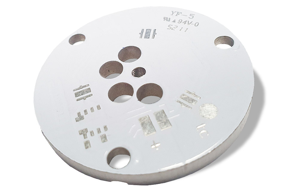
The former exotic, "aluminum printed circuit board" or "IMS board," has long since become a standard product, thanks in part to the LED revolution in the lighting industry.
"IMS" stands for "Insulated Metal Substrate." Wherever high-power LEDs emit a lot of heat, aluminum boards showcase their strengths by dissipating heat and ensuring a longer lifespan through reduced stress in application.
However, even standard products bring new challenges, and the requirements for aluminum printed circuit boards continue to rise alongside the ever-increasing goals for high-performance electronics and thermal management. The applications for aluminum-based boards now extend far beyond mere illumination - high-power heat management has permeated every corner of the electronics industry!
Keep a cool head - with IMS heat management PCBs
The challenges lie in mechanical requirements, as aluminum boards often need precise expansion with heat sinks, and the aluminum board constitutes only an integral part of the thermal management system. Deep milling or counterboring are typical mechanical enhancements for better integration into the finished assembly. Requirements for higher layer counts form the second front where aluminum printed circuit boards are becoming increasingly complex. For instance, the single-sided standard aluminum board, with aluminum as a carrier on one side, is manufactured as an aluminum core in the case of 2- or multi-layered PCBs.
The aluminum layer is thus integrated into the structure. With the necessary insulation for through-hole connections, not only various design rules need to be considered, but also special expertise is required in the manufacturing process to effectively and seamlessly bond such different materials together with high quality.


Options |
|---|
| Material properties | 1 to 12 W/mK, 38-100µm isolation |
| Material manufacturers | Ventec, BOYU, Polytronics, TCLAD (Bergquist) |
| Material thicknesses | 0,5 mm to 3,0 mm |
| Maximum PCB size | 428 x 568 mm², oversized PCBs on enquiry |
| Copper thicknesses | 35µm / 70µm |
| Layer count | 1 to 2 layers, multilayer (carrier or core) |
| Surface finishes | HAL-lead-free, HAL, ENIG, ENEPIG, OSP |
| Mechanical machining | routing, milling, scoring, jump scoring, countersinking, punching |
| Drill options | Isolated drills |
| Metallizations | none |
| Solder mask | Lacquer, high relexation lacquer, lacquer colors: green, black, red, blue, yellow, white, special colors (all RAL colors) and matt lacquers |
| Special prints | Peelable lacquer, carbon printing, UV reflection lacquer, silk screen printing |
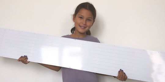
| Special technologies | Multilayer alu-IMS as carrier or core types, oversized IMS PCB >1000 mm |
| Quality Management & Certifications | ISO 9001, ISO 14001, UL, IPC2/IPC3, IATF 16949, EMPB, VDA2, PPAP, cross-sections (x-sections), measurements, declarations of conformity, data sheets, ESD packaging and more |
| Logistics | Framework orders, consignment stock, call-off stock, sea-air split orders, express delivery from 2 working days |
Definition: IMS PCB
IMS PCB stands for "Insulated Metal Substrate Printed Circuit Board". Since printed circuit boards connect electronic components and conduct electric currents, insulation from the aluminum carrier is important, as otherwise it would cause short circuits. Special, highly heat-conductive prepregs are used for this purpose. These consist of epoxy resin fiberglass fabric and fillers that are meant to improve heat dissipation. IMS PCBs work best when the thermal conductivity of this insulation layer is high. With high thermal conductivity, the heat generated on the PCB due to electric currents can be effectively dissipated through the insulation layer to the aluminum carrier. This effect ensures passive cooling of the electronics.
Advantages of IMS printed circuit boards
The advantages of IMS printed circuit boards lie in their ability to efficiently dissipate high heat from components. Heat can damage components or greatly accelerate the aging process. In extreme cases, components can desolder themselves due to heat during operation, causing the solder to become liquid again and the component to detach, resulting in a defective electronic system.
Advantages of IMS printed circuit boards:
- Efficiently dissipates heat from components
- Reduces stress on assemblies, increasing lifespan
- Thermal conductivity can be tailored to requirements
- Cost-effective manufacturing of the board
- Lightweight material
- Forms an optimal transition to other active or passive cooling methods
In some cases, the technical performance of aluminum IMS printed circuit boards can be surpassed by using copper IMS printed circuit boards, as the thermal conductivity of copper is significantly higher at approximately 360 W/mK compared to aluminum (approximately 220 W/mK).
Applications of insulated metal substrate PCB
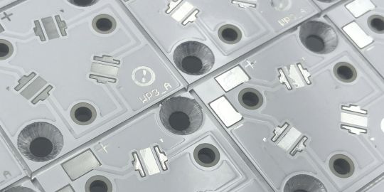
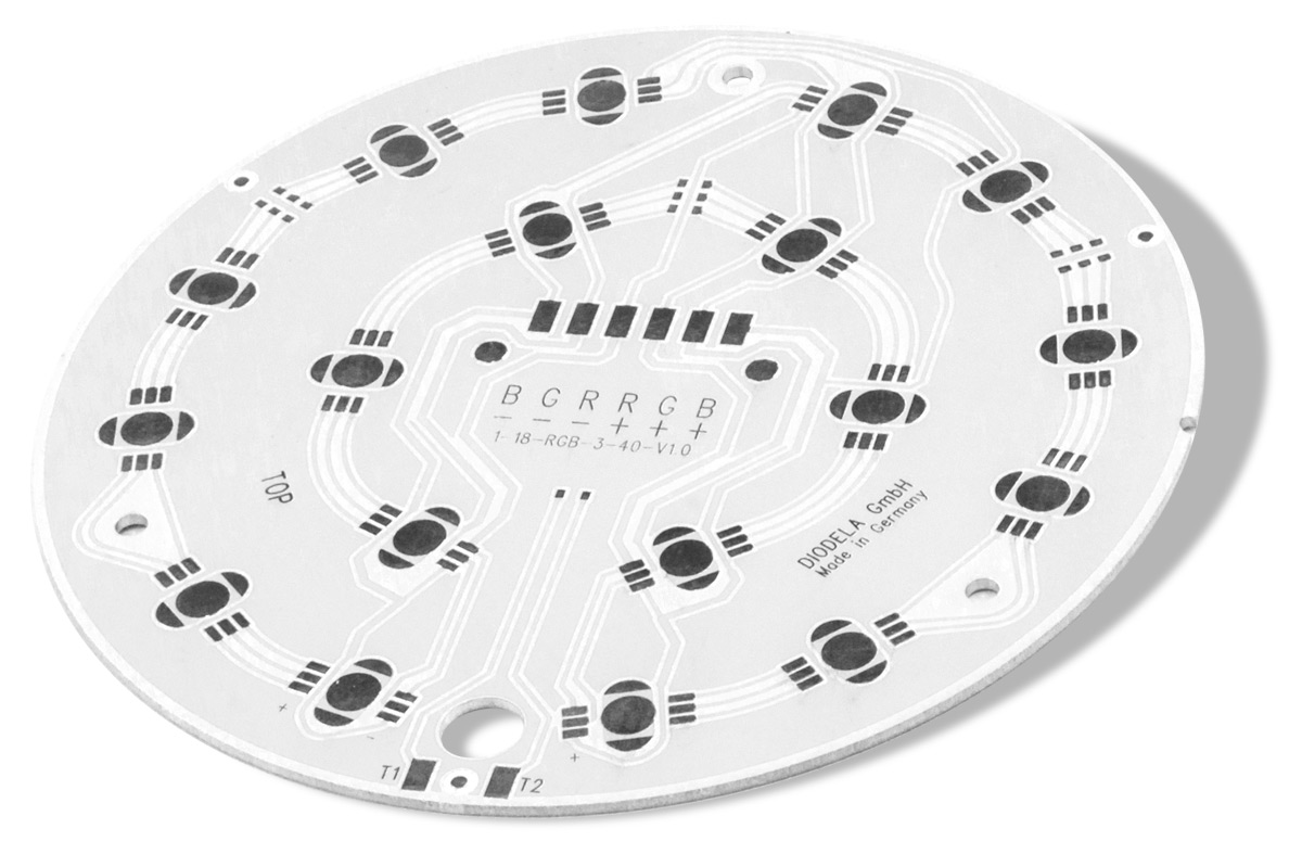
Traditional applications for aluminum IMS boards originally stemmed from the lighting industry. Aluminum PCBs experienced a significant boost with the advent of so-called power LEDs, as these emitted a substantial amount of heat. Nowadays, even power LEDs are often much more efficient and generate far less heat than a few years ago. Consequently, the lighting industry is frequently transitioning from pure IMS PCBs back to conventional and more affordable FR4 printed circuit boards.
In the automotive industry, IMS printed circuit boards find frequent application in engine control units, which are installed close to or even within the engine itself. The intense heat generated by the engine can be more effectively dissipated through the larger surface area of the aluminum board onto connected thermal management elements.
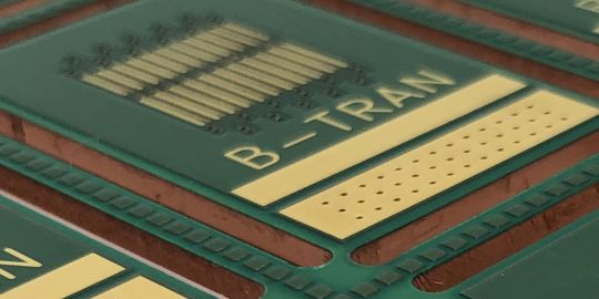
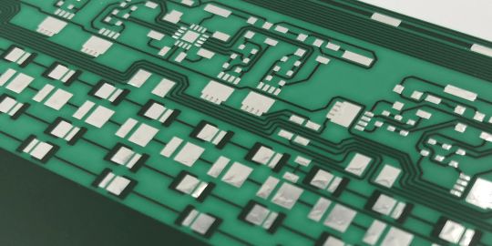
Further applications include power electronics, where extreme heat is produced by the circuitry itself and is dissipated without additional heat traps through IMS printed circuit boards. Additionally, in Solid State Relays (SSRs), the generated heat is directly conducted through the IMS board to the housing, resulting in passive cooling.
Types of IMS printed circuit boards
IMS-carrier vs. IMS-core
Like all printed circuit boards, IMS boards differ primarily in terms of layer count. While the vast majority of IMS PCBs are single-layer aluminum carrier boards, multi-layered configurations are becoming more common as well. When multi-layer FR4 boards are pressed onto an aluminum carrier, this is commonly referred to as, for example, 2-layer or 4-layer aluminum carrier PCBs. However, if the aluminum is integrated within the multilayer or the 2-layer board, it is referred to as aluminum core printed circuit boards.
In the case of IMS carrier boards, the manufacturing process of individual PCBs might seem relatively straightforward, but due to the asymmetry of the construction, warping can occur. The pressing process must be perfectly controlled as a result.
For IMS core printed circuit boards, the expertise lies in the pre-drilling and insulation of future vias, ensuring they do not hit and short-circuit the metal core on one hand, while not being overly insulated to avoid reducing the heat dissipating effect on the other.
For more interesting special technologies related to IMS printed circuit boards and much more, you can find them here.
Thermal Conductivity and TG of Insulation
Another characteristic is generally the used insulation prepreg. While standard FR4 has a thermal conductivity of about 0.4 W/mK, the insulation layers of IMS aluminum printed circuit boards start at 1.0 W/mK. Up to approximately 3.0 W/mK is common. Higher thermal conductivity values up to 12 W/mK are rare from many manufacturers but are available in our online calculation.
The glass transition temperature (TG) of aluminum-based insulated metal substrates (Alu-IMS) typically falls between TG120 and TG185 for TCLAD (Bergquist) materials. The reason for choosing a much lower TG120 for the insulation layer may seem unusual, but it is rooted in the differing coefficients of thermal expansion between the aluminum substrate and the copper layer. Opting for a lower TG120 makes the insulation layer become more "pliant" earlier, which reduces stresses throughout the structure and relieves the assembly at higher temperatures. A perceived disadvantage can, under certain circumstances, turn into an advantage.
Aluminum PCB vs. copper PCB
The final major distinction of IMS boards is the type of metal substrate used. While aluminum clearly dominates in electronics applications due to its low cost and lightweight nature, there are also copper IMS printed circuit boards. An advantage of copper IMS boards is that a conductive connection to the metal carrier can be established through a via. This is not possible with aluminum IMS. Additionally, aluminum IMS boards cannot be manufactured with chemically deposited tin, as aluminum contaminates the tin bath chemistry. With copper IMS, on the other hand, this is easily achievable.
The production of our IMS printed circuit boards
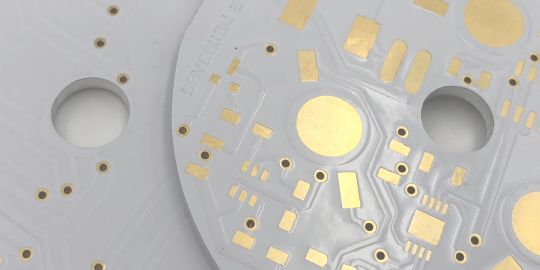
Conventional single-layer IMS printed circuit boards largely follow the production process of regular single-layer FR4 boards. The main differences lie in the mechanical processing, as both drilling and milling must be conducted at a slower pace than with FR4. Failure to adhere to specific parameters for mechanical processing can quickly lead to burr formation. Further intricacies arise during chemical gold plating (ENIG or ENEPIG), as the aluminum must be masked everywhere to prevent contact with the gold bath, which could lead to contamination.
Significant differences from conventional PCB manufacturing occur in the production of 2- or multi-layer aluminum-core IMS printed circuit boards, where the aluminum is embedded within the board. For this, the pure aluminum layer needs to be pre-drilled larger at the sites of future vias and then isolated with a paste. This pre-drilled aluminum layer is then pressed within the multilayer, and the vias are drilled through the insulated areas to prevent shorts to the aluminum core.
Buy affordable IMS PCB online directly from manufacturer
You can find aluminum boards with a variety of options from professional industrial production in our online calculation. In addition to different thermal conductivity values, material thicknesses, copper thicknesses, and various solder mask colors, there are a range of delivery time options. The popular TCLAD (Bergquist) HPL material with only 38µm insulation is also available in our online calculation!
IMS stands for "Insulated Metal Substrate," referring to printed circuit boards with an integrated but electrically insulated metal layer (usually aluminum, occasionally copper). IMS printed circuit boards have significantly higher thermal conductivity compared to FR4 boards due to the integrated metal layer. They are commonly used when high temperatures are generated either within the electronics themselves or in their surroundings. Thanks to the improved thermal management provided by IMS boards, the lifespan of electronics can be substantially increased with appropriate usage.
IMS printed circuit boards can be distinguished based on both the type of metal used (aluminum or copper) and the position of the metal layer within the layer stack. When the metal is on the outside (contactable), they are referred to as IMS carrier boards. If the metal is pressed within the layers of the board during fabrication, they are known as IMS core boards. In the latter case, the metal is visible only at the edges and is not fully accessible from one side.
Aluminum IMS printed circuit boards offer several advantages over conventional FR4 boards in electronics applications with high heat generation:
- Heat is dissipated from components
- This reduces stress on the electronics and extends their lifespan
- Thermal conductivity can be chosen higher according to requirements
- Aluminum IMS boards are very cost-effective due to their wide use
- Aluminum is a very lightweight material
- The aluminum can be directly mounted onto a conducting heat sink using thermal paste or similar.
IMS printed circuit boards primarily differ in the base material used. While conventional boards are made from an epoxy resin fiberglass material (referred to as "FR4"), aluminum IMS boards have a base made from a common aluminum alloy (e.g., AL5052 with >3% magnesium content). The thickness of this aluminum base typically matches the common PCB thicknesses of 0.8mm or 1.5mm. Between this aluminum carrier and the copper, there is an insulating epoxy resin layer with thermal conductivities that usually surpass the standard FR4 with 0.4 W/mK. Common values are 1.3 W/mK or 2.0 W/mK, and 3.0 W/mK. Higher thermal conductivities are rare, but with Leiton, values of up to 12.0 W/mK are available in the online calculation.
The aluminum layer of an IMS printed circuit board efficiently dissipates heat from so-called hot spots by a significant margin and spreads it across the wide surface of the aluminum layer. Hot spots are dangerous when specific components generate very high levels of heat during operation. Such heat can cause lasting damage to the component or even lead to self-desoldering. In general, IMS aluminum boards significantly enhance the lifespan of electronics in applications with extreme heat generation. Aluminum IMS boards are particularly effective when additional passive or even active cooling mechanisms are attached to the rear aluminum layer, allowing for even better heat dissipation from the circuit.
Aluminum IMS boards are employed whenever efficient thermal management is needed. Aluminum IMS printed circuit boards assist in evenly distributing ambient heat or heat generated by the electronics themselves across the aluminum carrier substrate, thereby avoiding so-called "hot spots." Hot spots, or heat in general, reduce the lifespan of electronic components. For example, the lifespan of an electrolytic capacitor doubles when the peak temperature is lowered from 95°C to 105°C. Common application areas for aluminum IMS PCBs include:
- (High-intensity) LED circuits/illumination
- Power electronics / Transformers
- Motor controls (in environments with extreme heat)
In short: Kind of. IMS stands for "Insulated Metal Substrate," so the part of the word involving "metal" is accurate. However, the IMS abbreviation doesn't indicate the position of the metal substrate. Many manufacturers incorrectly use the term "metal core" when they actually mean "metal carrier." A core is situated in the middle of the layer stack, while a carrier is positioned on one side. The significant majority of IMS printed circuit boards consist of only one copper layer with aluminum on the other side, separated by an insulating prepreg, making them strictly metal carrier boards. Only when the aluminum is placed within the layer stack (e.g., copper-insulation-aluminum-insulation-copper) should one refer to it as a metal core board.
IMS aluminum printed circuit boards generally cost slightly more than pure FR4 boards. In the prototype phase, this is often due to the lower utilization of production panels in the sharing principle (combining different orders on a production panel), while in mass production, it's due to the slightly higher material costs of aluminum compared to FR4. In terms of processing, single-layer FR4 boards and aluminum IMS boards are nearly identical in terms of cost. However, there is a slightly increased effort (cost) associated with aluminum in the mechanical processes (milling and drilling), as slower work is required here and tools wear out more quickly.
Aluminum IMS base materials differ in many aspects. Besides the overall thickness and copper layer, the thickness of the insulation layer (prepreg) between aluminum and copper, as well as its thermal conductivity, are the most apparent. In general, the thinner this insulation layer and the higher the thermal conductivity, the better heat can be dissipated from the copper layer into the aluminum. Caution: A very thin insulation layer often has disadvantages in terms of breakdown strength!
Further differences exist regarding the glass transition temperature (TG) of the used prepreg. Aluminum and copper can, in principle, withstand extremely high temperatures of several hundred degrees, but the weakest link in the chain is this insulation. The TG for conventional aluminum materials is around 130°C, resulting in a maximum operating temperature of about 100°C. High-performance materials such as TCLAD (Bergiquist) HPL-3015 have a TG of 185°C with a maximum continuous operating temperature of 140°C.
As the name suggests, the greatest difference lies in the used material. But what does that mean for the technical performance of each IMS printed circuit board? The advantages of copper IMS boards primarily stem from the even higher thermal conductivity of the metal (copper: ~320 W/mK versus aluminum ~240 W/mK). This implies that heat in the metal carrier is even more efficiently distributed or dissipated from hot spots. However, this advantage comes with some disadvantages.
On the one hand, copper weighs significantly more at 9 g/cm³ compared to aluminum's 2.8 g/cm³, making it an exclusion criterion for certain products. On the other hand, the higher weight of copper, coupled with generally two to three times higher raw material costs than aluminum, results in a raw material cost increase of a factor of 6 to 10 for an equivalently sized board. Considering factors like shipping weight, availability, and the fact that copper processes more slowly in mechanical fabrication, a price premium of a factor of 10 or more emerges, which doesn't quite match the 1.3-fold gain in thermal conductivity. Therefore, copper IMS boards remain a high-tech variant that should be considered only after aluminum IMS technology has been fully utilized.
However, a technological advantage of copper IMS boards lies in the possibility of galvanically connecting (via plating) copper in the carrier with drill holes (vias) or soldering on the copper carrier. Both of these are not feasible with aluminum IMS boards.

Elektronik-Design
- Expertise through active exchange
- Expertise through training and further education
- ISO 9001:2015 Quality Management
- ISO 14001:2015 Environmental Management

- UL for rigid FR4 PCBs
- UL for flexible circuit boards
- UL for aluminum IMS boards


