

battery cell balancing (CCS)
Nickel tabs | CCS PCBs | Battery cell balancing | Cell contacting
Nickel tabs on flexible printed circuits
for cell balancing and cell contacting (CCS)
Nickel tabs are small nickel plates that are soldered onto a flexible printed circuit (FPC) and welded to the individual cells of a battery pack. This assembly is called a cell balancing PCB or Cell Connection System (CCS, also Cell Contacting System). It contacts the cells, senses voltage and temperature and routes these signals to the battery management system (BMS). Typical tabs are 0.20 mm or 0.30 mm thick and consist of over 99 percent nickel, depending on the alloy.
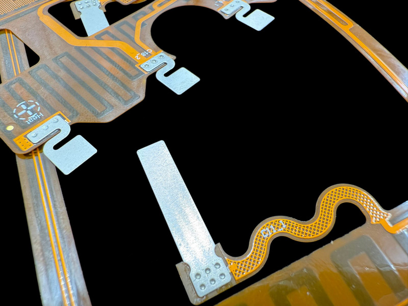
Battery cells expand over their operating life. Flexible geometries in the nickel tabs, for example a serpentine shape, compensate this change in length and relieve welded and soldered joints. Nickel is the material of choice here because it can be soldered with tin and welded to the cell in several processes: resistance spot welding, laser welding or ultrasonic welding. Copper is unfavourable at this point because it dissipates and reflects heat strongly and is therefore difficult to weld reliably. The connection to the circuit board is additionally made through perforations in the tab, through which the tin rises during soldering and reinforces the joint. A purely flat soldered connection without holes is significantly less stable and can float during the soldering process, causing positional inaccuracies. Typical hole diameters are 0.80 mm to 1.0 mm; several solder feed-throughs per tab increase strength and tin flow.
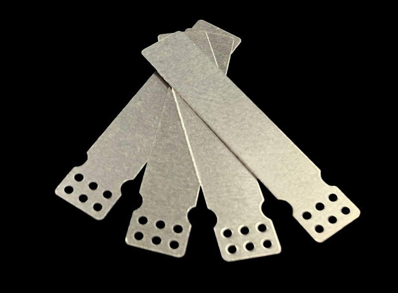
The tab geometry can be chosen almost freely. Overly narrow or filigree sections must be avoided, as the tabs break there. The nickel tabs on the FPC are the first step. If their cross-section is not sufficient for the load current, aluminium plates can additionally be welded on. These form their own current path from cell to cell. The flex circuit itself does not become more current-capable and remains the signal layer. The assembly can then be brought into a permanent, defined 3D shape by PET thermoforming (PET, polyethylene terephthalate). Both processes are suitable for series production but cause high one-time setup costs. The comparison with classic busbar technology follows below.
From CCS to integrated module
A CCS with nickel tabs on FPC is the first step and covers cell contacting, voltage sensing and temperature measurement. The cross-section of the thin nickel tabs is not sufficient for the load current. Welding on aluminium plates does not make the flex circuit itself more current-capable either. The aluminium plates form their own current path and carry the main current directly from cell to cell, bypassing the circuit board. The FPC remains the signal layer. The assembly thus takes over the busbar function without a separate cell connector being mounted. The subsequent PET thermoforming brings the assembly into a permanent, defined 3D shape. PET thermoforming is shaping and insulation, not a joining technology. The transition from CCS to busbar therefore does not lie in the PET step but in the current-carrying cross-section. The result is a cell contacting module that combines the information and power level in one component.
When is a CCS with nickel tabs the right choice?
A CCS with nickel tabs is the right choice when individual cells of a battery pack need to be contacted, monitored and balanced. Typical situations: when discrete wiring or cable harnesses in the pack are to be replaced, when installation space and weight are critical, when many cells must be connected reproducibly and automatically, or when voltage and temperature sensing are to be combined with the cell connection in one assembly. If the connector only carries high currents permanently and no cell monitoring is required, a classic solid busbar is sufficient.
For one-off samples without a planned series, a CCS is rarely economical due to the high one-time setup costs. Classic cable harnesses are recommended here.
Applications
Comparison: CCS with nickel tabs versus solid busbar
CCS and busbars are not competing products but two functional levels in a battery module. The matrix shows the common differences.
| Characteristic | CCS with nickel tabs on FPC (Leiton) | Solid busbar / cell connector |
|---|---|---|
| Primary function | Cell contacting, voltage sensing, temperature measurement, balancing connection. | Main current path, power connection between cells and blocks. |
| Conductor and material | Thin nickel tabs (0.20 to 0.30 mm), soldered on, on copper FPC. | Solid cross-section of copper or aluminium, in the millimetre range. |
| Current-carrying capacity | Limited, for sense signals and moderate currents. Nickel is a poorer conductor than copper. | High, carries the pack load current. |
| Signals and sensing | Integral part: sense lines, NTCs, ID tracking. | Usually not included, pure power level. |
| Cell connection | Resistance spot, laser or ultrasonic welding of the tabs, soldering to the FPC. | Laser welding, screwing or bonding. |
| Shaping | Thin and flexible, can be brought into a permanent 3D shape by PET thermoforming. | Rigid, shaped by stamping and bending. |
| Role in the module | Information and balancing level. | Power level. |
Advantages
Important notes:
Nickel is a poorer conductor than copper. The current-carrying capacity of the tabs is therefore determined by cross-section and geometry and must be designed project-specifically. Overly narrow or filigree sections in the tab geometry must be avoided, as the tabs break there.
The nickel content depends on the alloy and must be defined project-specifically.
Cell balancing assemblies are generally setup-intensive. Even without optional processes, the overlength of the flex circuit and the assembly of the tabs require numerous fixtures, plus a stamping tool and welding and soldering fixtures. Welding on aluminium contacts and PET thermoforming increase setup costs further. For transport and handling of the usually long and filigree CCS assemblies, custom PET packaging trays are typically required, which also count towards the one-time setup costs. All these one-time costs (NRE, non-recurring engineering) only amortise in series production. For samples alone, the unit price is correspondingly higher.
Certificates of conformity such as RoHS and REACH are available on request.
Request and calculate CCS with nickel tabs
What we need for a solid quotation: Gerber data or a comparable format (ODB++, KiCad, Eagle etc.) for the flex layout, technical drawings of the nickel tabs (we are happy to suggest improvements) and a bill of materials (BOM) with the additional components, usually NTCs and always a connector. Plus quantity and target series volume. Optional processes such as aluminium plates, PET thermoforming or custom packaging trays should be mentioned early, as they determine tooling and setup costs.
Why Leiton: technical consulting from tab geometry to the integrated module, custom tools and fixtures, CAM review (CAM, Computer Aided Manufacturing) and series capability from one source, 100 percent testing with resistance measurement and ID tracking, personal availability. Leiton places each project appropriately depending on price, lead time and technology, from samples to series.
A CCS makes sense when individual cells need to be contacted, monitored and balanced and installation space and weight matter. A solid busbar remains the right choice when a simple current path carries high currents permanently and no cell monitoring is required on the connection. The detailed criteria are listed in the comparison table.
Nickel can be welded reliably to the cell and soldered to the circuit board with tin. Copper dissipates and reflects heat strongly, which makes it difficult to weld reproducibly. The lower conductivity of nickel is compensated by cross-section and geometry; for high load currents, aluminium plates are additionally welded on.
Mainly the one-time setup costs (NRE): stamping tool, welding and soldering fixtures, general fixtures and, where applicable, tooling for aluminium plates, PET thermoforming and custom packaging trays. Added to this are the layer stack and length of the flex circuit, the number of tabs and sensing points, and the quantity over which the one-time costs amortise.
There is no fixed threshold; the one-time costs dominate. The unit price drops significantly in series production. Samples make sense as a preliminary stage of a planned series; as one-offs they are correspondingly more expensive. If no series is planned, the feasibility of conventional cable harnesses should be checked first.
The assembly is called CCS (Cell Connection System, also Cell Contacting System) or cell balancing PCB. All of these mean the same product: nickel tabs on a flexible printed circuit for contacting and monitoring individual cells. Not meant are nickel strips as raw material for pack building, or solid cell connectors and busbars, which are a different technology.

Elektronik-Design
- Expertise through active exchange
- Expertise through training and further education

- ISO 9001:2015 Quality Management
- ISO 14001:2015 Environmental Management

- UL for rigid FR4 PCBs
- UL for flexible circuit boards
- UL for aluminum IMS boards


