Rigid-Flex PCB | Printed Curcuit Board
Rigid-Flex PCB (Printed Circuit Boards)
Rigid-Flex Printed Circuit Boards - Unlimited Possibilities
When the two worlds of "rigid" and "flexible" meet in a printed circuit board, a rigid-flex PCB (RFPCB) is born. It combines the classic rigid board (PCB) with the somewhat "more exotic" flexible circuit board (FPC), opening up entirely new possibilities, such as miniaturization or significantly increased reliability in applications involving extensive movement. The rigid-flex PCB adds a third dimension to the assembly without sacrificing ease of processing. By integrating the flexible circuit board into the rigid structure, the number of connectors is reduced. This saves costs on connectors, frees up space, and greatly surpasses most connectors in terms of reliability. Although rigid-flex PCBs may cost more than rigid or flexible boards, when considering all the advantages together, they often prove to be a more cost-effective alternative.
Rigid-Flex PCBs for Everyone
Many developers hesitate when considering designing their PCB as a rigid-flex board. Uncertainty regarding the required design rules plays a role, as well as the myth that rigid-flex PCBs are very expensive. Both prejudices can be quickly dispelled in most cases. In terms of design, there are only a few differences to consider compared to rigid or flexible PCBs. We are happy to provide quick and straightforward advice, for example, through a phone call. For cost estimation, rough information is sufficient so that unnecessary time is not invested in a potential rigid-flex design without knowing the price. For a meaningful comparison, it is important to consider not only the PCB costs but also the complete Bill of Materials (BOM), as rigid-flex PCBs can eliminate the need for cables, connectors, and assembly components.


Options |
|---|
| Material properties | FR4 TG150, TG170, glueless polyimide (PI) |
| Material manufacturers | ITEQ, ShengYi |
| Material thicknesses | 0,5mm to 3,0mm |
| Maximum PCB size | 230x370mm², other oversizes on request |
| Copper thicknesses | 18µm / 35µm / 55µm /70µm |
| Layer count | 2 to 12 layers |
| Surface finishes | ENIG, ENEPIG, hard gold |
| Mechanical machining | Milling, laser cutting, scoring (v-cut), jump-scoring, chamfering, depth milling, countersinking |
| Drill options | Micro vias, blind vias, laser vias, stacked vias, press-fit technology |
| Metallizations | Edge metallization, stamp contours, half-opens, slotted holes, plated slots |
| Solder mask | Coverlay, flex varnish, mixture "flex varnish & coverlay" Paint colors: green, black, yellow, white |
| Special prints | silkscreen |
| Special technologies | Stiffeners PI or FR4, 3M adhesive, lift-off areas, dimples, component carriers, “book-binding” technique, special layer stack-ups, shielding-foil |
| Quality Management & Certifications | ISO 9001, ISO 14001, UL, IPC2/IPC3, IATF 16949, EMPB, VDA2, PPAP, cuts, measurements, declarations of conformity, data sheets, ESD packaging |
| Logistics | Framework orders, consignment stock, call-off stock, sea-air split orders |


Definition: rigid-flex PCB
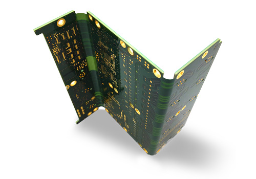
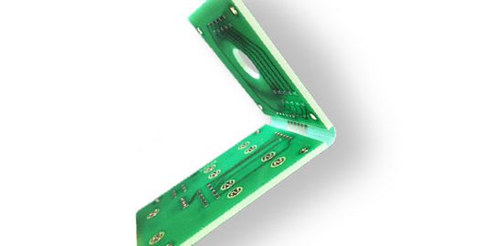
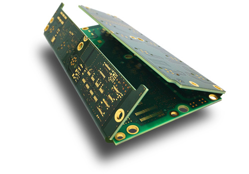
The Rigid-Flex PCB (RFPCB), also known as a rigid-flex circuit board, is a hybrid of conventional rigid boards and flexible circuit boards. In this design, the flexible circuit layers are integrated into the rigid board, allowing them to extend directly from the rigid area. As a result, a rigid-flex PCB serves as a stable support structure and provides flexible connections for electronic components in three-dimensional or movable applications.
Advantages of rigid-flex printed circuit boards
The advantages of rigid-flex PCBs are truly versatile:
- 3D electronic interconnection
- Direct connection between rigid and flexible boards
- Reduction of connectors (cost and space savings)
- Increased reliability by minimizing connectors (eliminating loose connections)
- Integration of multiple boards into a single assembly
- Miniaturization through higher compactness
- Dynamic load capacity of flexible areas
- Stability for complex components on rigid sections
- Diverse and flexible combinations of multiple rigid and flexible PCBs in an RFPCB
Material & properties of rigid flex PCB
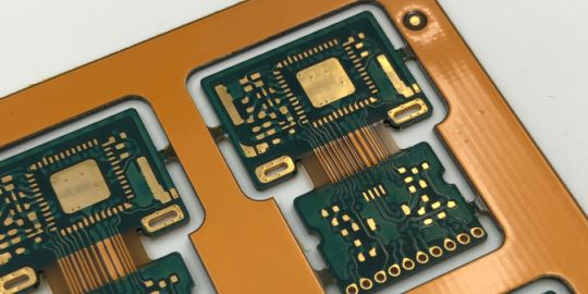
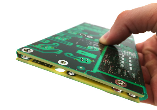
Rigid-flex PCBs consist of rigid epoxy fiberglass boards and flexible polyimide circuitry. The stable and durable lamination of these significantly different materials requires strict adherence to process specifications in PCB manufacturing. When these specifications are followed, rigid-flex PCBs are extremely resilient and robust. On one hand, they are highly solderable and easily automated in assembly, similar to rigid PCBs. Moreover, they provide a sturdy platform for component mounting in their application.
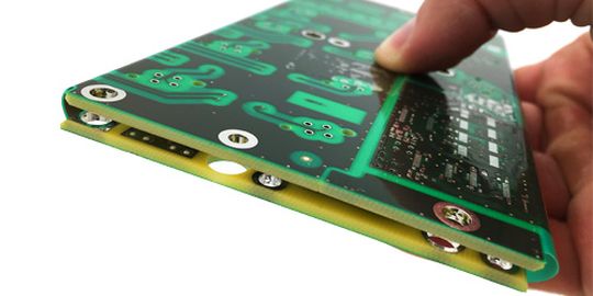
The flexible portions of rigid-flex PCBs, on the other hand, offer versatile possibilities for three-dimensional installation within enclosures or even dynamic movement of parts of the circuitry. The bending radii can be relatively tight, often just a few millimeters. However, bending areas should not be located directly at the transition from the rigid to the flexible section to prevent the formation of cracks.
The temperature resistance of rigid-flex PCBs typically falls within the normal range of TG150°C, with a maximum operating temperature of approximately 130°C.
Applications of rigid-flex PCB
There are a range of application areas for rigid-flex PCBs. In general, they are used when either high assembly compactness (miniaturization) is required or when parts of the electronics need to be movable. In particular, connectors used to link individual PCBs through cables or flexible circuitry often occupy significant space. By integrating the rigid-flex transitions directly into the board, it allows for a significant compression of the entire electronics. In complex and tight installation situations, rigid-flex PCBs are often the right choice.
Another widely used application is to connect various electronic modules over longer distances while maintaining dynamic movability. Often, sensors or switches that are located at a certain distance from the main board are connected through a flexible section. While these connections could also be made using ZIF/LIF connectors and flex boards when space is not an issue, such constructions are more susceptible to loose connections, especially under vibrations or shocks. In this case, a direct connection from the rigid electronic PCB to the dynamically stressed flex area is the reliable option.
Types of flexible printed circuit boards (FPC)
Flexible and rigid-flex PCBs are closely related. Below, we will explain the differences briefly and concisely.
Flexible printed circuits FPC
As the name suggests, flexible circuit boards FPC are inherently flexible. While certain areas can be partially stiffened, the conductive traces and the entire substrate are primarily designed to be flexible and bendable. Flexible PCBs are typically 1- or 2-layered, with relatively simple complexity. They are often used for interconnecting electronic components rather than supporting complex circuitry. This is primarily because flexible multilayer PCBs with more than 2 layers become less flexible and lose their inherent advantages. Moreover, complex designs with multilayer routing usually require additional components that should not be placed in flexible areas or should be stabilized with stiffeners. Therefore, for more complex designs with flexible requirements, rigid-flex PCBs are a suitable choice.
For cost-sensitive projects, flexible PCBs with stiffeners can serve as an alternative to rigid-flex boards. We are happy to provide early-stage guidance on what to consider in such cases.
Rigid-flexible printed circuit boards RFPCB
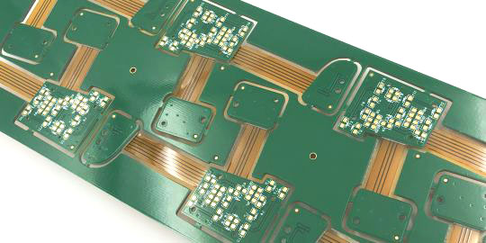
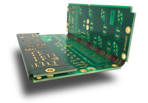
Rigid-flex PCBs are a combination of rigid and flexible circuit boards. Multiple rigid boards can be interconnected with flexible intermediate pieces, providing a high degree of freedom. Unlike pure flexible PCBs, rigid-flex boards typically exhibit high component density and routed traces in the rigid areas. As a result, rigid-flex PCBs are usually multilayered, with four or more layers.
FPCBs are classified based on the position of the flexible layers in the construction. They can be classified as "outer" or "inner" layers. For example, in a 4-layer rigid-flex PCB, the rigid areas consist of four layers, while the flexible areas are usually one or two layers. "Outer" means the flexible layers are positioned directly on the top or bottom. "Inner" means the flexible layers are only located in layers 2 and/or 3.
This classification provides important insights into the complexity, effort, and pricing of the manufacturing process. Many rigid-flex PCB manufacturers simply label them as "2R+2F" (2 rigid + 2 flexible layers). However, this does not indicate whether the flexible layers are positioned on the outside or inside. A more detailed specification of the position of the flexible layers in the construction can be achieved through the following convention.
Classification of a 4-layer multilayer with 2 flexible layers ("2R+2F"):
- Outer flexible layers: 4LA2
- Inner flexible layers: 4LI2
The first number indicates the total number of layers, in this case, "4 layers." This is followed by the position of the flexible layers, where "A" represents "outer" (German “A” for “aussen” = “outer”) and "I" represents "inner." (German: “innen”) This convention can be combined in various ways, for example, 8LI1, where "inner" flexible layers require a symmetrical layer arrangement and are positioned in the middle. The specific layer positions can be determined from the layout data. Similarly, for a 4LA2, it is irrelevant from the production perspective whether the flexible layers are on the top or bottom.
The production of our printed circuit boards
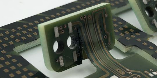
The manufacturing process of rigid-flex PCBs can become extremely complex depending on the design. However, in general, it is initially similar to that of normal multilayer PCBs. To produce boards with both rigid and flexible areas, additional and sometimes elaborate steps are required. Firstly, the areas that will become flexible must be separated from the prepregs (PP) that bond the layers of the multilayer PCB. So the prepregs are pre-cut separately, unlike in standard multilayers where they are fully pressed over the entire surface.
When planning the layer stackup, it is crucial to consider that the flexible layers span the entire construction of the rigid portion.
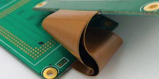
Another significant difference in the manufacturing process of rigid-flex PCBs is the subsequent process of milling or “depth-routing”. The partially bonded flexible layers are milled or routed to a depth just before reaching the flex layer at the points where the prepreg was removed prior to pressing. This process gives the rigid-flex PCB its characteristic feature of directly connecting rigid and flexible areas.
Rigid-flex PCBs can become highly complex, and thus, the differences mentioned above are general and simplified distinctions.
Buy affordable rigid-flex PCB online directly from manufacturer
As one of the very few worldwide, Leiton provides an online calculation tool for rigid-flex PCBs. Rigid-flex multilayers up to 6 layers can be easily and quickly calculated and ordered online. The construction allows for a maximum of 2 flexible layers, positioned either internally or externally. For higher-layer and more complex rigid-flex PCBs, inquiries can be made. We are happy to provide early-stage design process consultation.
Rigid-flex PCBs are rigid-flex printed circuit boards that consist of rigid and flexible areas in one circuit board. In electronics, they serve to carry and connect electrical components (mostly 3-dimensionally). Rigid-flex PCBs are made of FR4 (epoxy resin and glass fiber) in the rigid areas, while the flex areas are made of polyimide.
Flexible printed circuit boards are usually flexible in their entirety, i.e. bendable. Rigid-flex circuit boards contain areas that are completely rigid. Theoretically, flexible printed circuit boards (flex PCB) can also contain so-called stiffeners, which make them rigid at certain points. However, with flexible printed circuits, these rigid reinforcements are always glued on afterwards and can therefore neither have plated vias through this rigid area, nor can components be soldered onto these rigid reinforcements. Rigid-flex printed circuit boards, on the other hand, can be completely plated through in the rigid area and these areas are PCBs that can be fully assembled on both sides.
The advantages of rigid-flex circuit boards are:
- Connection of rigid and flexible printed circuit boards
- Omission of plug contacts (saves money and space)
- Increased reliability due to fewer connectors (no loose contacts)
- Merge multiple PCBs into a single assembly
- Miniaturization by using all 3 dimensions
- High dynamic load capacity in flex areas
- Stability for complex components on the rigid areas
- Large combination possibilities of rigid and flexible boards in a rigid-flex PCB
Rigid-flex circuit boards are usually used when complex electronic functions have to be combined with a high three-dimensional packing density, or when different electronic systems have to be reliably connected to one another via flexible paths. Robots are a simple example of complex three-dimensional electronic circuits that need to be mobile.
The rigid areas of Rigid-Flex circuit boards are usually made of FR4, a glass fiber epoxy resin mixture. The flexible areas are mainly made of polyimide (PI), with small amounts of epoxy used as an adhesive. A combination of lacquer (on the rigid areas) and polyimide epoxy masking film (on the flexible areas) is commonly used as a solder stop. In addition, copper is the conductive material. Nickel-gold surfaces (ENIG or ENEPIG) are mostly used for better solderability of the free contacts, but tin is also possible.
The flexible areas are mainly made of polyimide (PI). In the rigid areas, these polyimide layers are laminated with epoxy resin glass fiber sheets (FR4) to form a multilayer. The flexible PI layers can be inside the pressed multilayer or outside. Combinations or multiple flexible layers in the rigid area can also be integrated into complex rigid-flex structures (e.g. “bookbinding” technique).
Rigid-flex circuit boards are tested in exactly the same way as conventional rigid FR4 circuit boards. In addition to various visual inspections during production, an automatic optical inspection (AOI) and an electrical test (ET) are usually carried out at the end. Under certain circumstances, pull-off tests or shear tests can also be carried out on the flexible layers to check stability. Another destructive test to ensure stability is "HAL-dipping". A rigid-flex circuit board representative of the manufactured batch is immersed in tin several times at a temperature of 260°C for approx. 10 seconds to check whether the layers are loosening (delaminating).
The costs of printed circuit boards of all kinds and types primarily depend primarily on the following factors:
- Quantity Manufactured
- Size of the circuit board
- Complexity of the circuit board (e.g. number of layers)
- Production time
Considering all these factors, the cost of a rigid-flex PCB can actually range from a few cents to several thousand euros. A rule that is almost always applied is that with the same factors mentioned above, rigid-flex circuit boards always cost more than purely rigid or flexible circuit boards.
The production time of rigid-flex printed circuit boards, depends heavily on the quantity and complexity. In general, express prototypes can be produced within a few days. Larger series take a few weeks. In principle, however, the production time for rigid-flex PCBs is longer than for normal rigid or flexible circuit boards. This is due to various additional processes required for production.
The possible bending radius of rigid-flex circuit boards refers only to the flexible areas, as only these can be bent. The bendability of this flexible area depends on the number of layers, copper density and polyimide material thickness chosen. The fewer layers, less copper and thinner the material, the higher the bendability. A rough calculation aid is available in our toolbox.

Elektronik-Design
- Expertise through active exchange
- Expertise through training and further education
- ISO 9001:2015 Quality Management
- ISO 14001:2015 Environmental Management

- UL for rigid FR4 PCBs
- UL for flexible circuit boards
- UL for aluminum IMS boards


