

rigid PCBs
Prepreg on FR4 | black FR4 | embedded traces | instead of solder mask | coverlay alternative | PCB manufacturing
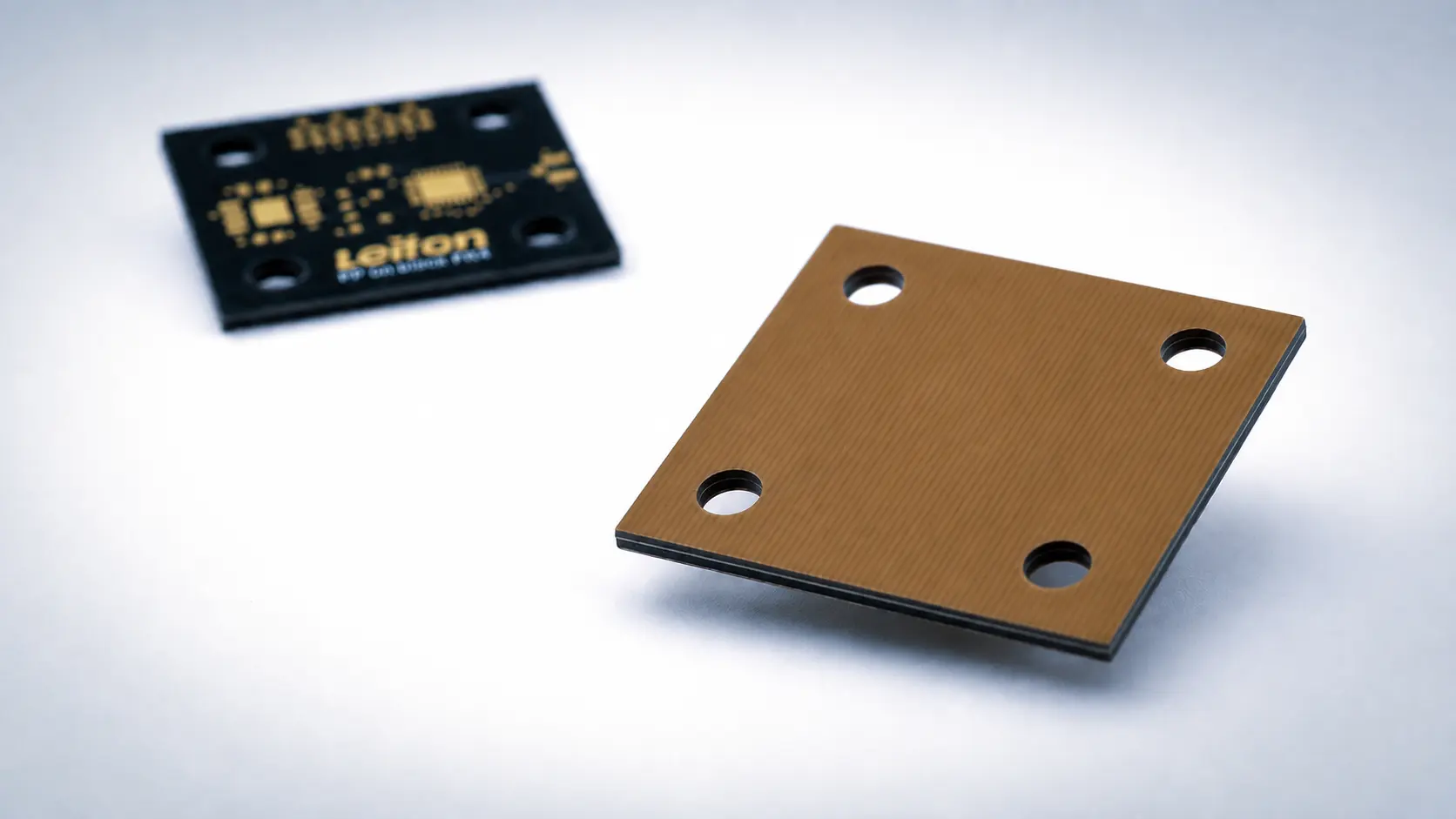
Pressed-on prepreg on black FR4: embedded conductors instead of solder mask
Prepreg on FR4: embedded conductors instead of solder mask
In this build-up, FR4 prepreg (pre-impregnated glass fabric, the base material of every multilayer lamination) is pressed over the finished outer layer. During pressing, the resin fills the conductor pattern completely and cures into the same laminate system as the core. The result is a PCB whose former outer layers are fully embedded in FR4. The thickness of the cover is freely selectable, from around 50 µm per ply to several hundred µm.
The decisive difference to solder mask and coverlay: per the design standard IPC-2221 (IPC, standards body of the PCB industry), the embedded conductors count as internal conductors. The minimum electrical spacings for internal conductors per IPC-2221, section 6.3, Table 6-1 apply. The difference is substantial. Example for the 301 to 500 V range: 0.25 mm internal, 2.5 mm external uncoated, 0.8 mm external under solder mask. Creepage distances along the surface are eliminated as well, because there is no surface left between the conductors. In their place stands solid insulation made of a qualified base material. For this material system, the dielectric strengths are tested in both directions: the electric strength perpendicular through the laminate and the breakdown voltage parallel to the laminations. Exactly this horizontal value is missing for solder mask and for the adhesive layer of a coverlay.
The cover is always applied full-area the entire surface. Openings for component assembly and electrical contacts are not possible. The additional pressing cycle increases thickness, price and lead time. For standard assemblies without insulation requirements, solder mask remains the right choice.
Thermal Prepreg on FR4: Electrical Insulation with Improved Thermal Conductivity
Thermal prepregs are basically used in the same way as conventional FR4 prepregs, but are optimized for significantly higher thermal conductivity. For this purpose, the resin system is modified with thermally conductive, electrically insulating fillers. During lamination, the resin encapsulates the conductor pattern and, after curing, forms a solid insulation layer that transfers heat through the PCB structure much more effectively than conventional FR4.
The key advantage is the combination of electrical insulation and targeted heat dissipation. Heat generated by conductors or power components can be transferred through the thermal prepreg layer to underlying copper areas, heavy-copper layers, or other heat-spreading structures.
Depending on the material system, significantly higher thermal conductivity than standard FR4, which is generally considered a thermal insulator, can be achieved. Thermal prepregs are available with thermal conductivities of 1–3 W/mK and typically have a thickness of around 100 µm.
Thermal prepregs are therefore particularly suitable for power electronics, LED applications, and assemblies with localized hot spots, where high electrical insulation and improved heat dissipation within an FR4 construction are required simultaneously. For this purpose, the fully assembled PCBs are usually bonded directly to metal bodies using a thermally conductive adhesive to further optimize heat dissipation.
When is pressed-on prepreg used on rigid PCBs?
If a defined horizontal dielectric strength is required between adjacent conductors, the pressed-on prepreg is the reliable solution. The gap is filled with the qualified resin system. A typical example: the separation between high-voltage potential and measurement tap in an 800 V battery system with tight packaging. If the available space is not sufficient for the creepage distances per IEC 60664-1 (the standard for insulation coordination), embedding solves the problem in line with the standard. The creepage distance is the shortest path between two conductors along the insulation surface. At 800 V and pollution degree 2, the standard requires 4.0 to 8.0 mm depending on the material group. Embedded conductors have no surface. The dimensioning of solid insulation takes the place of the creepage distance.
If the assembly operates in a polluted environment or under condensation, the closed laminate surface protects it. Condensation means: during temperature changes the surface drops below the dew point, condensed water settles and makes surface spacings conductive. Embedded conductors are not affected. If creditable solid insulation with data sheet values is required, solder mask is not sufficient in practice. The laminate system provides dielectric strengths tested per IPC test methods.
The reverse also holds: for standard assemblies, solder mask remains the economical choice. For thin covers under abrasion, the coverlay is the suitable alternative. For thermal applications, we also offer thermally conductive prepregs with thermal conductivities of 1–3 W/mK. Standard base material is regular FR4. On request, Leiton combines the build-up with dyed-through black FR4, for example for light-tight or visually uniform assemblies.
Applications
Comparison: pressed-on prepreg versus solder mask, coverlay and potting
The pressed-on prepreg competes with standard solder mask, with the laminated coverlay and with potting after assembly. The matrix shows the positioning, with links to the respective special-technology pages.
| Solution | Typical use | When it is the right choice |
|---|---|---|
| Pressed-on FR4 prepreg | Outer layers with insulation requirements, fully embedded in laminate. On request on dyed-through black FR4. | When solid insulation with tested values is required, including parallel to the surface. The conductors count as internal per IPC-2221. |
| Solder mask | Standard for almost all rigid PCBs, finely structured by photolithography. | When there is no abrasion or insulation requirement. As insulation, solder mask is often not accepted, because coating thickness on conductor edges and freedom from pinholes are not specified. |
| Coverlay on rigid FR4 | Thin laminated polyimide film for outer layers under abrasion or with insulation requirements perpendicular to the film. | When the surface is under mechanical stress or a thin, defined insulation layer is sufficient. Details on the special-technology page. |
| Conformal coating | Coating of the fully assembled board against moisture, condensation and contamination. | When the complete assembly including components must be protected, not the bare board surface. |
| Potting | Complete encapsulation of the assembled board in its housing. | When components and connections must be enclosed as well. Heavy, not repairable and thermally demanding. The prepreg solves the insulation task at board level already. |
Prepreg styles and thicknesses
The cover thickness is set via glass style and number of plies. Any target thickness can be reached by combining several plies. The values are guide values per pressed ply and depend on the resin system and on the resin demand of the conductor pattern. The glass transition temperature (Tg) of the prepreg is freely selectable, from standard Tg 130°C to high-Tg 180°C.
| Prepreg style (glass style) | Thickness per pressed ply, guide value | Resin content, typical | Typical use as cover |
|---|---|---|---|
| 106 | approx. 50 µm | high (approx. 70 %) | Thin cover, good resin filling of fine conductor patterns. |
| 1080 | approx. 65 µm | medium to high (approx. 60 %) | Standard for thin cover plies with reliable edge filling. |
| 2113 Thermo PP | approx. 100 µm | medium (approx. 55 %) | Standard for thermal applications. |
| 2116 | approx. 115 µm | medium (approx. 55 %) | Medium thicknesses, balanced between filling and stiffness. |
| 7628 | approx. 190 µm | low (approx. 45 %) | Thick covers and fast thickness build-up in multi-ply constructions. |
On appearance: the cured prepreg is translucent. Below around 100 µm cover thickness, the conductor pattern remains visible under the cover. From around 100 µm prepreg thickness it can no longer be seen. If a uniform surface is required, choose a thicker cover accordingly.
Dielectric strength: defined perpendicular and horizontal
The central advantage of the build-up is the dielectric strength in both directions. Solder mask and coverlay adhesive insulate horizontally without a specified value. With pressed-on prepreg, the space between adjacent conductors is filled with the resin-glass system of the laminate. For rigid base materials, the breakdown voltage parallel to the laminations is tested separately (IPC-TM-650 2.5.6, reported in kV at a defined electrode spacing). Perpendicular, the electric strength of the laminate applies. Both values are stated in the base material data sheet. They are short-time breakdown values from material testing, not permissible operating voltages.
| Direction | Value | Test basis |
|---|---|---|
| Perpendicular through the prepreg | Electric strength of the laminate system per data sheet, usual minimum per IPC-4101: 30 kV/mm. Short-time value, not an operating voltage. | IPC-TM-650 2.5.6.2 |
| Parallel to the laminations (horizontal) | Breakdown voltage of the laminate system per data sheet, usual minimum per IPC-4101: 40 kV at 25.4 mm electrode spacing. Short-time value, not an operating voltage. | IPC-TM-650 2.5.6 |
| Between adjacent embedded conductors | Resin-filled gap without air voids at the conductor edges. Dimensioned via the conductor spacing as an internal layer. | IPC-2221, spacings for internal conductors |
For continuous operation, the two short-time values from the table are derated substantially on a project-specific basis, to account for aging, moisture and partial discharge. The void-free embedding of the conductors by the reflowing prepreg resin has a positive effect here: at conductor edges under solder mask, air pockets often remain, where partial discharge sets in. During pressing, the resin fills these edges completely.
Standards framework and voltage systems
The build-up operates within a clear normative framework. The table shows the relevant standards and their role. Whether the build-up can be credited as basic or reinforced insulation in an end device is decided by the applicable product standard. Leiton provides the build-up, thicknesses and material values for this assessment.
| Standard / regulation | Relevance for the build-up |
|---|---|
| IPC-2221, section 6.3, Table 6-1 | Design standard for minimum electrical spacings on PCBs, graded by voltage and conductor location. Embedded conductors fall into category B1 (internal). Example for 301 to 500 V: 0.25 mm internal (B1), 2.5 mm external uncoated (B2), 0.8 mm external under a permanent polymer coating (B4). |
| IPC-4101 with IPC-TM-650, methods 2.5.6 and 2.5.6.2 | Specification of rigid base materials with the associated test methods. Method 2.5.6 measures the breakdown voltage parallel to the laminations between electrodes spaced 25.4 mm apart, required minimum 40 kV. Method 2.5.6.2 measures the electric strength perpendicular through the material, required minimum 30 kV/mm. The actual values are stated in the data sheet of the material used. |
| IEC 60664-1 | Insulation coordination for equipment within low-voltage systems. Defines clearances, creepage distances and the dimensioning of solid insulation, depending on rated voltage, pollution degree and material group (via the CTI). Example creepage distance at 800 V and pollution degree 2: 4.0 to 8.0 mm depending on material group (Table F.4). Embedded conductors are instead dimensioned as solid insulation. |
| IEC 62368-1 | Safety standard for information, audio and video technology equipment. Distinguishes basic, supplementary and reinforced insulation. Solid insulation is verified via insulation distances and withstand voltage tests. Reinforced insulation is required between the mains side and accessible low-voltage circuits. |
| IEC 60601-1 | Safety standard for medical electrical equipment. Patient protection is assessed via MOPP (Means of Patient Protection), operator protection via MOOP (Means of Operator Protection). Each protection level has its own requirements for creepage, clearance, solid insulation and test voltages. |
| ISO 6469-3 / ECE R100 | Electrical safety of electric vehicles. Voltage class B covers above 60 V up to 1500 V DC and thus the 400 V and 800 V vehicle networks. Requirements include protection against direct contact and insulation resistances of at least 100 ohms per volt for DC systems and 500 ohms per volt for AC systems. |
Advantages in comparison
The table compares the prepreg build-up with the two alternatives, including the points where solder mask or coverlay remain in the lead.
| Criterion | Pressed-on FR4 prepreg | Solder mask | Coverlay |
|---|---|---|---|
| Conductor status per IPC-2221 | Internal, substantially reduced spacings. | External. | External with permanent coating (category B4). |
| Horizontal dielectric strength | Laminate value, tested per IPC-TM-650 2.5.6. | No specified value. | No specified value, residual adhesive thickness undefined. |
| Creepage distance | Eliminated, solid insulation applies. | Required per IEC 60664-1. | Reduced, but remains a surface consideration. |
| Insulation thickness above the conductors | Freely selectable, approx. 50 µm to several hundred µm. | Approx. 10 to 25 µm, undefined at conductor edges. | 25 or 50 µm polyimide plus adhesive. |
| Voids at conductor edges | Resin-filled, favorable for partial discharge behavior. | Air pockets at edges possible. | Adhesive flows, residual thickness above conductors undefined. |
| Impedance behavior | Defined dielectric above the conductors (embedded microstrip), reproducible impedance. The cover lowers the impedance and is factored into the stackup. | Mask thickness varies, impedance effect hard to calculate. | Film defined, adhesive thickness above conductors undefined. |
| Assembly of covered areas | Not possible, the cover remains full-area. | Unrestricted, pads remain open. | Only in open areas. |
| Surface | Glass-reinforced, glass-hard, abrasion-resistant. | Sensitive to abrasion. | Polyimide, highly abrasion-resistant but soft. |
| Current-carrying capacity | As an internal layer, reduced (no convection). | As an external layer. | Close to an external layer. |
On impedance behavior: embedded conductors form an embedded microstrip. Instead of a varying mask thickness, a dielectric with defined thickness and defined permittivity lies above the conductors. The impedance drops due to the cover and must be factored into the layer stackup. In return, it is reproducible and independent of environmental influences at the surface.
Option: dyed-through black FR4
On request, dyed-through black FR4 (glass-reinforced epoxy base material) serves as the base material. This is a visual option, not a functional one. Unlike black solder mask, the entire substrate is black, including the edges. The material is light-tight, UL-listed and, with a glass transition temperature (Tg) of 130°C, comparable to standard FR4. From stock: 0.6 mm, 1.0 mm and 1.6 mm with 35 µm copper, special thicknesses at short notice. Details on the black FR4 page.
Important notes:
Covered areas cannot be assembled or soldered. The cover is applied full-area, assembly and contacting lie outside the covered areas. The current-carrying capacity of embedded conductors is lower than that of exposed conductors, because convection is lost. For high currents, check the cross-section. The additional pressing cycle increases overall thickness, price and lead time compared to standard solder mask. Rework on embedded conductors is not possible. Below around 100 µm cover thickness, the conductor pattern remains visible through the translucent prepreg, above around 100 µm it does not. The prepreg is freely selectable with glass transition temperatures from 130°C to 180°C. The optional black core material is available with Tg 130°C; check the material where high-Tg is required. Whether the build-up can be credited as basic or reinforced insulation depends on the end-device standard and is the customer's responsibility. Compliance documents such as RoHS and REACH are available on request.
Request and calculate the prepreg build-up
What we need for a reliable quotation: layout data (ODB++, Extended Gerber, KiCAD or similar), the areas to be covered, the required insulation or voltage specification (operating voltage, test voltage, applicable standard if any), desired cover thickness and glass transition temperature, layer stackup and copper thicknesses, quantity and schedule.
Leiton places projects where they fit best in terms of price, lead time and technology. Depending on the project, prepreg build-ups are manufactured in Germany or in Asia.
Why Leiton: engineering advice on the insulation concept across solder mask, coverlay and prepreg, experience with embedded build-ups from multilayer production, black FR4 as an option from stock in three standard thicknesses, prototype to series, personal contact instead of a ticket system.
Because only the prepreg embeds the conductors completely in a qualified laminate system. Solder mask and coverlay adhesive insulate horizontally without a specified value. With prepreg, the gap between the conductors is filled with the tested resin system. In addition, the conductors count as internal, with the correspondingly smaller spacings.
IPC-2221 distinguishes spacings for external and internal conductors. Embedded conductors no longer have a free surface. Creepage and clearance distances are eliminated, the spacings for internal layers apply. This allows considerably more compact layouts at the same voltage.
For the laminate system, the breakdown voltage parallel to the laminations is tested per IPC-TM-650 2.5.6; the usual minimum per IPC-4101 is 40 kV at 25.4 mm electrode spacing. The permissible operating voltage is designed project-specifically and considerably lower, derated for aging, moisture and partial discharge.
Any. The cover is built from the standard glass styles 106, 1080, 2113, 2116 and 7628, from around 50 µm to 190 µm as a single ply, correspondingly thicker with several plies. Note: the prepreg is translucent. Below around 100 µm cover thickness the conductor pattern remains visible, above around 100 µm it disappears visually.
If a combination of electrical insulation and targeted heat dissipation is required, so-called thermal prepregs are used. They are available with thermal conductivities of 1–3 W/mK and typically have a thickness of around 100 µm.
The glass transition temperature (Tg) of the prepreg is freely selectable from 130°C to 180°C. The optional black core material is available with Tg 130°C. For an all-high-Tg build-up, combine high-Tg prepreg with a high-Tg core material in standard finish.
The coverlay is the thin solution for abrasion and for insulation requirements perpendicular to the film. The prepreg is the thick, homogeneous solution when values are also required horizontally or creepage distances are to be eliminated. Leiton offers both processes; the coverlay has its own special-technology page.
Yes, with an adapted design. Embedded conductors form an embedded microstrip with a defined dielectric instead of a varying mask thickness. The impedance drops due to the cover and is factored into the layer stackup. The result is more reproducible than a mask-covered microstrip.
That is decided by the applicable end-device standard, for example IEC 60664-1, IEC 62368-1 or IEC 60601-1, and ISO 6469-3 in vehicles. Leiton supplies the defined build-up with thicknesses and material values as the basis. The normative assessment in the device rests with the customer.
The additional pressing cycle, the area to be covered, prepreg style and number of plies, panel format and quantity. Add one-time setup costs (NRE, Non-Recurring Engineering). Full-area covers are the most economical. Reliable prices result from the layout data.
For visual reasons. The dyed-through substrate is completely black, including the edges, and light-tight. Technically it behaves like standard FR4 with UL listing and Tg 130°C. If no visual requirement exists, the build-up is available on regular FR4.

Elektronik-Design
- Expertise through active exchange
- Expertise through training and further education

- ISO 9001:2015 Quality Management
- ISO 14001:2015 Environmental Management

- UL for rigid FR4 PCBs
- UL for flexible circuit boards
- UL for aluminum IMS boards


